
9.3. Hard Disk Drives and Solid State Drives
9.3.1. Files on Secondary Storage
A programmer typically views a random access file stored on secondary storage as a contiguous series of bytes, with those bytes possibly combining to form data records. This is called the logical file. The physical file actually stored on a drive is usually not a contiguous series of bytes. It could well be in pieces spread all over the disk. The file manager, a part of the operating system, is responsible for taking requests for data from a logical file and mapping those requests to the physical location of the data on disk. Likewise, when writing to a particular logical byte position with respect to the beginning of the file, this position must be converted by the file manager into the corresponding physical location on the disk. To gain some appreciation for the the approximate time costs for these operations, you need to understand the physical structure and basic workings of a disk drive.
Disk drives and solid state drives are often referred to as direct access storage devices. This means that it takes roughly equal time to access any record in the file. This is in contrast to sequential access storage devices such as tape drives, which require the tape reader to process data from the beginning of the tape until the desired position has been reached. As you will see, the hard disk drive in particular is only approximately direct access: At any given time, some records are more quickly accessible than others.
9.3.2. Hard Disk Drives
9.3.2.1. Hard Disk Drive Architecture
A hard disk drive is composed of one or more round platters, stacked one on top of another and attached to a central spindle. Platters spin continuously at a constant rate. Each usable surface of each platter is assigned a read/write head or I/O head through which data are read or written, somewhat like the arrangement of a phonograph player’s arm “reading” sound from a phonograph record. Unlike a phonograph needle, the disk read/write head does not actually touch the surface of a hard disk. Instead, it remains slightly above the surface, and any contact during normal operation would damage the disk. This distance is very small, much smaller than the height of a dust particle. It can be likened to a 5000-kilometer airplane trip across the United States, with the plane flying at a height of one meter!
A hard disk drive typically has several platters and several read/write heads, as shown in Figure 9.3.1 (a). Each head is attached to an arm, which connects to the boom. The boom moves all of the heads in or out together. When the heads are in some position over the platters, there are data on each platter directly accessible to each head. The data on a single platter that are accessible to any one position of the head for that platter are collectively called a track, that is, all data on a platter that are a fixed distance from the spindle, as shown in Figure 9.3.1 (b). The collection of all tracks that are a fixed distance from the spindle is called a cylinder. Thus, a cylinder is all of the data that can be read when the arms are in a particular position.
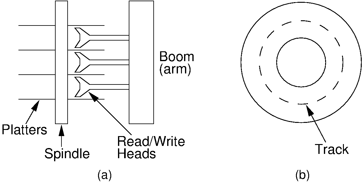
Figure 9.3.1: Disk drive schematic. (a) A typical disk drive arranged as a stack of platters. (b) One track on a disk drive platter.
Each track is subdivided into sectors. Between each sector there are inter-sector gaps in which no data are stored. These gaps allow the read head to recognize the end of a sector. Note that each sector contains the same amount of data. Because the outer tracks have greater length, they contain fewer bits per inch than do the inner tracks. Thus, about half of the potential storage space is wasted, because only the innermost tracks are stored at the highest possible data density. This arrangement is illustrated by Figure 9.3.2 (a). Disk drives today actually group tracks into zones such that the tracks in the innermost zone adjust their data density going out to maintain the same radial data density, then the tracks of the next zone reset the data density to make better use of their storage ability, and so on. This arrangement is shown in Figure 9.3.2 (b).
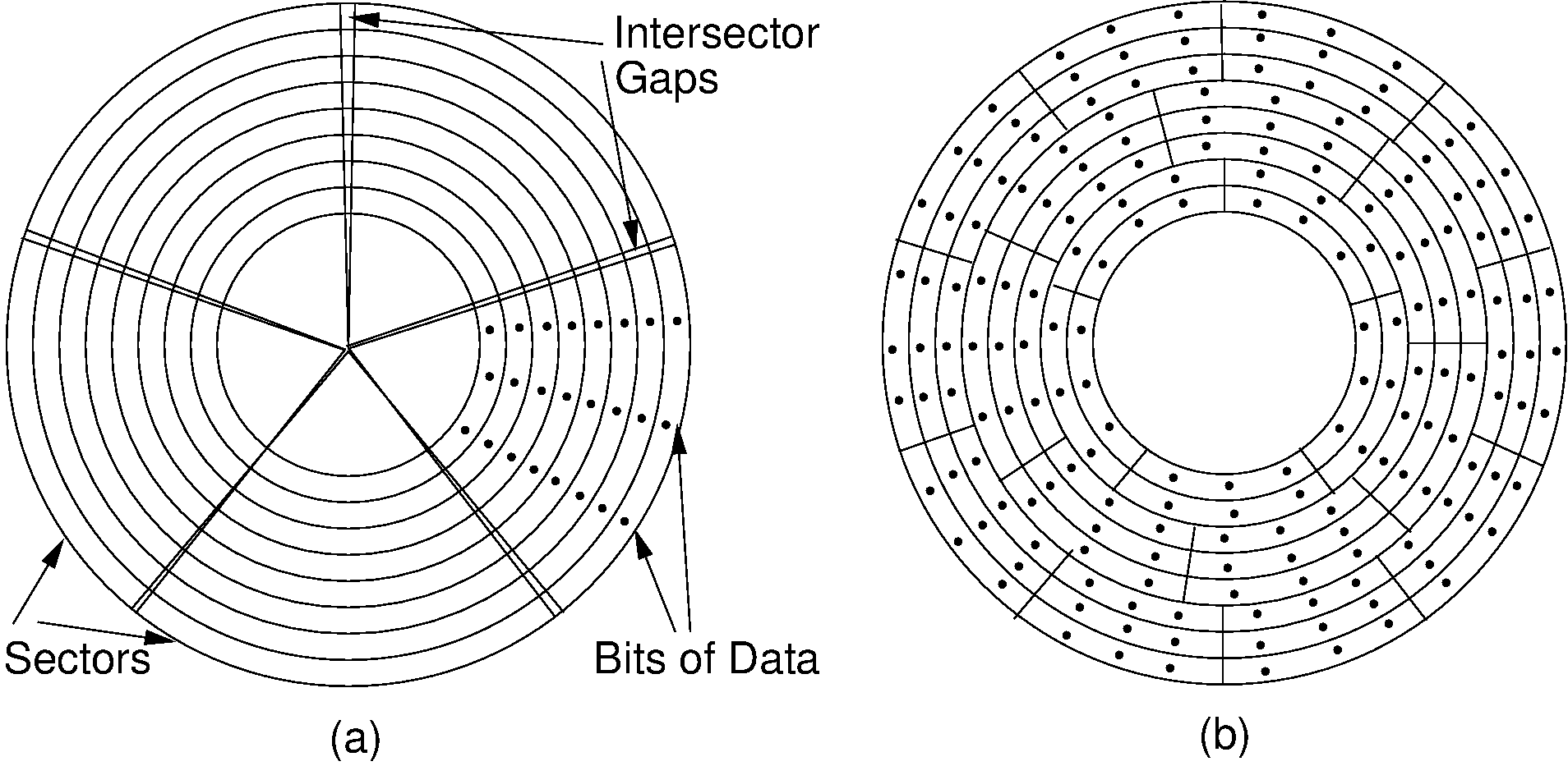
Figure 9.3.2: The organization of a disk platter. Dots indicate density of information. (a) Nominal arrangement of tracks showing decreasing data density when moving outward from the center of the disk. (b) A “zoned” arrangement with the sector size and density periodically reset in tracks further away from the center.
In contrast to the physical layout of a hard disk, a CD-ROM consists of a single spiral track. Bits of information along the track are equally spaced, so the information density is the same at both the outer and inner portions of the track. To keep the information flow at a constant rate along the spiral, the drive must speed up the rate of disk spin as the I/O head moves toward the center of the disk. This makes for a more complicated and slower mechanism.
Three separate steps take place when reading a particular byte or series of bytes of data from a hard disk. First, the I/O head moves so that it is positioned over the track containing the data. This movement is called a seek. Second, the sector containing the data rotates to come under the head. When in use the disk is always spinning. At the time of this writing, typical disk spin rates are 7200 rotations per minute (rpm). The time spent waiting for the desired sector to come under the I/O head is called rotational delay or rotational latency. The third step is the actual transfer (i.e., reading or writing) of data. It takes relatively little time to read information once the first byte is positioned under the I/O head, simply the amount of time required for it all to move under the head. In fact, disk drives are designed not to read one byte of data, but rather to read an entire sector of data at each request. Thus, a sector is the minimum amount of data that can be read or written at one time.
In general, it is desirable to keep all sectors for a file together on as few tracks as possible. This desire stems from two assumptions:
Seek time is slow (it is typically the most expensive part of an I/O operation), and
If one sector of the file is read, the next sector will probably soon be read.
Assumption (2) is called locality of reference, a concept that comes up frequently in computer applications.
Contiguous sectors are often grouped to form a cluster. A cluster is the smallest unit of allocation for a file, so all files are a multiple of the cluster size. The cluster size is determined by the operating system. The file manager keeps track of which clusters make up each file.
In Microsoft Windows systems, there is a designated portion of the disk called the File Allocation Table, which stores information about which sectors belong to which file. In contrast, Unix does not use clusters. The smallest unit of file allocation and the smallest unit that can be read/written is a sector, which in Unix terminology is called a block. Unix maintains information about file organization in certain disk blocks called inodes.
A group of physically contiguous clusters from the same file is called an extent. Ideally, all clusters making up a file will be contiguous on the disk (i.e., the file will consist of one extent), so as to minimize seek time required to access different portions of the file. If the disk is nearly full when a file is created, there might not be an extent available that is large enough to hold the new file. Furthermore, if a file grows, there might not be free space physically adjacent. Thus, a file might consist of several extents widely spaced on the disk. The fuller the disk, and the more that files on the disk change, the worse this file fragmentation (and the resulting seek time) becomes. File fragmentation leads to a noticeable degradation in performance as additional seeks are required to access data.
Another type of problem arises when the file’s logical record size does not match the sector size. If the sector size is not a multiple of the record size (or vice versa), records will not fit evenly within a sector. For example, a sector might be 2048 bytes long, and a logical record 100 bytes. This leaves room to store 20 records with 48 bytes left over. Either the extra space is wasted, or else records are allowed to cross sector boundaries. If a record crosses a sector boundary, two disk accesses might be required to read it. If the space is left empty instead, such wasted space is called internal fragmentation.
A second example of internal fragmentation occurs at cluster boundaries. Files whose size is not an even multiple of the cluster size must waste some space at the end of the last cluster. The worst case will occur when file size modulo cluster size is one (for example, a file of 4097 bytes and a cluster of 4096 bytes). Thus, cluster size is a tradeoff between large files processed sequentially (where a large cluster size is desirable to minimize seeks) and small files (where small clusters are desirable to minimize wasted storage).
Every disk drive organization requires that some disk space be used to organize the sectors, clusters, and so forth. The layout of sectors within a track is illustrated by Figure 9.3.3. Typical information that must be stored on the disk itself includes the File Allocation Table, sector headers that contain address marks and information about the condition (whether usable or not) for each sector, and gaps between sectors. The sector header also contains error detection codes to help verify that the data have not been corrupted. This is why most disk drives have a “nominal” size that is greater than the actual amount of user data that can be stored on the drive. The difference is the amount of space required to organize the information on the disk. Even more space will be lost due to fragmentation.
9.3.2.2. Hard Disk Drive Access Cost
When a seek is required, it is usually the primary cost when accessing information on disk. This assumes of course that a seek is necessary. When reading a file in sequential order (if the sectors comprising the file are contiguous on disk), little seeking is necessary. However, when accessing a random disk sector, seek time becomes the dominant cost for the data access. While the actual seek time is highly variable, depending on the distance between the track where the I/O head currently is and the track where the head is moving to, we will consider only two numbers. One is the track-to-track cost, or the minimum time necessary to move from a track to an adjacent track. This is appropriate when you want to analyze access times for files that are well placed on the disk. The second number is the average seek time for a random access. Unfortunately, it is often difficult to get these numbers for a given device. But typical times are about 1-2 ms for the track-to-track time, and an average seek time of about 5-10 ms. This has not changed much in a number of years, even though the storage density (and hence, total capacity rating that you see) has gone up over the years.
For many years, typical rotation speed for disk drives was 3600 rpm, or one rotation every 16.7 ms. By 2025, most disk drives had a rotation speed of 7200 rpm, or 8.3 ms per rotation. A few lower-priced drives run at 5400 RPM, and high-performance drives run at 10,800 RPM. When reading a sector at random, you can expect that the disk will need to rotate halfway around to bring the desired sector under the I/O head, or 4.2 ms for a 7200-rpm disk drive.
Once under the I/O head, a sector of data can be transferred as fast as that sector rotates under the head. If an entire track is to be read, then it will require one rotation (8.3 ms at 7200 rpm) to move the full track under the head. But that is a large amount of data. Far more typical is reading one sector.
As an example, one recent disk with a nominal size of 2TB has approximately 1.8TB of usable space divided among 3 platters with 6 heads. These contain a total of 62,016,065 tracks, or approximately 10,000,000 tracks per suface Each track has 63 sectors per track, and so that amount of actual read time for a given sector (once the seek is done and the data rotate under the head) is quite low.
This information should give you a sense for how much the layout of data on the drive will affect performance. If every record requires a random seek of 5-10 ms and rotational delay of another 4 ms, that is much slower than reading a track containing, say, 64 records for that same seek time and rotational delay.
9.3.3. Solid State Drives
Solid State Drives work quite differently from Hard Disk Drives. They do not require any physical movement to reach data, and as a consequence, they are far closer to being truly random access in that the time to get a byte of information is roughly the same no matter where it is on the drive.
Getting detailed information about a HDD (such as track-to-track times) can be difficult. Getting meaningful information about SSD performance seems to be even harder. The typical vendor specs for SDD relate to total theoretical throughput of data read per second, or number if I/O operations per second. This might have some value for the manager of a data center. For a programmer of an application that has a loop of reading some data and making a decision before reading more data, none of those reported values are helpful for predicting performance. To make matters worse, SSDs degrade in their performance fairly quickly over time.
Probably the most useful performance metric for an individual programmer is the the latency time to get the next piece of information. Where this is typically around 10ms for a HDD, this more like .1ms for the SSD. So the SSD is roughly two orders of magnitude faster in this scenario. From a system perspective, the SSD is good at handling multiple data requests at once. In contrast, the HDD has difficulty even in a typical situation like copying a file from one place to another. This causes constant contention for the I/O heads as they move between the two files. None of that is an issue for the SSD.
SSD typical smallest read size is the same as for a HDD: About 4K bytes these days. So it makes sense for an application using either storage type to buffer data at the block level. That is, given that a read is going to give you 4K bytes of data, you want to write the application so that future read requests will likely make use of this information that you already have available.
One of the most important metrics for SSD performance is the “queue depth”. This is the amount of I/O access that can be done before needing to get a decision from the first I/O access. In other words, if we have to read a piece of data and then decide from what we read where to go next, that is termed QD1. This is generally the least efficient data access paradigm for SSD. SSDs are really good at dealing with parallel I/O requests, which in the limit might be referred to as QD32 in performance specs.